AJH - Ring SM

AJH - Ring SM is an instant retro-analog drone machine. Combining the sound of a set of classic oscillators and a high-quality ring modulation circuitry will provide sounds that are convincing enough for a lot of years to come.
€291.60
Availability: Out of stock
SKU
ajhrsm

AJH - Ring SM is an instant retro-analog drone machine. Combining the sound of a set of classic oscillators and a high-quality ring modulation circuitry will provide sounds that are convincing enough for a lot of years to come.


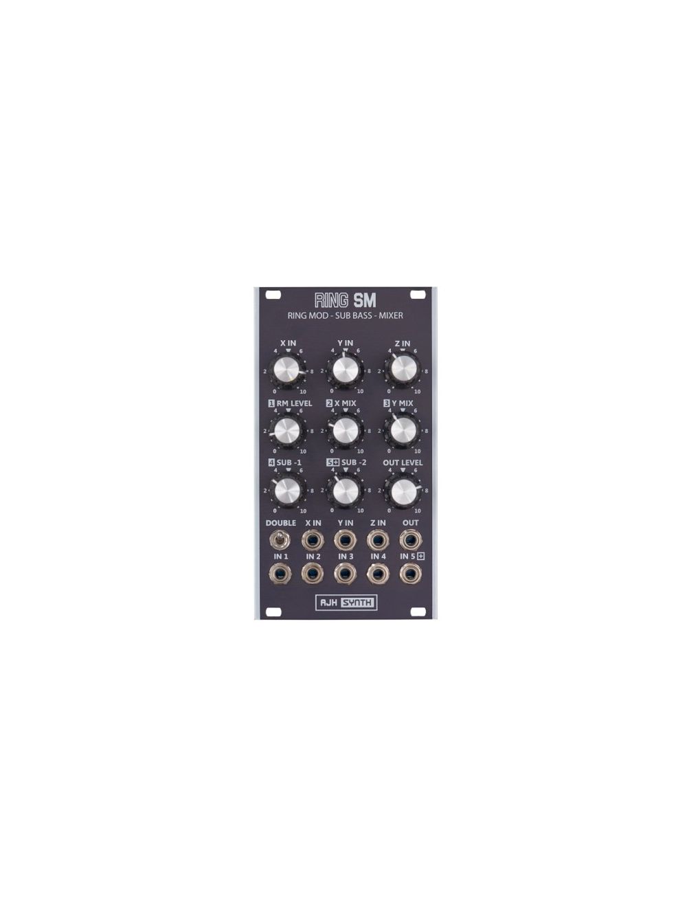
The AJH - Ring SM is four modules in one:

A very unique and warm sounding ring modulator with three inputs, X, Y & Z It is a vintage design based entirely on a discrete transistor core, and includes an extra, resonant Z modulator input. It also has a Frequency Doubling switch, from a single triangle or sine wave input an octave +1 output is generated

Two independent Sub Bass generators with very fast tracking, creating -1 Octave and -2 Octaves from the X input. These are not simple square wave subs, they generate specially shaped waveforms and are useful up to 1kHz – they have a much lower harmonic content than square wave subs, designed to have more power and sit much better in a mix.

A five input DC coupled mixer based on the discrete transistor CP3 modular design dating back to 1974. The Outputs of the ring modulator, X and Y inputs and Sub Bass outputs are routed to the mixer by default – plugging a patch cable into any of the mixer inputs defeats this normalising and allows it to be used as a regular 5 channel mixer for both audio and control voltages.

A clipping / distortion module – input 5 of the mixer is considerably “hotter” than the other four mixer channels and will clip the signal as soon as it hits threshold level. If a DC bias voltage is added the signal is shifted and this allows positive or negative asymmetric clipping of the waveform.

Download Manual

Module Width: 14hp

Module Depth: 24mm (34mm with power cable)
Current Usage: 55mA Positive, 50mA Negative

In Depth

The AJH Synth Ring SM is a unique new Eurorack module that features a three input discrete transistor Ring Modulator core, two shaped sine Sub Bass generators and a five channel discrete transistor mixer with extra distortion capability; all within 14HP of Eurorack Modular panel space.

1: Ring Modulator The RING SM module is quite unique because, unlike other manufacturers, we do not use a cheap "off the shelf" ring modulator or balanced modulator integrated circuit as the basis of our design, instead our ring modulator circuit is based on a discrete transistor AC coupled Gilbert Cell design dating back to the early 1960's. The overload and distortion characteristics are rather different and more musically useful, and we have also been able to add a third Z input in addition to the usual Carrier (X) and Modulator (Y) inputs seen on other ring modulator designs. The Z Input is actually a second modulator input that has a different phase relationship with the ring modulator core and it can produce a more resonant sound when it is used. All three inputs (X, Y, and Z) can be used simultaneously.

Mixer Integration

By using mixer input normalising the Ring Modulator has been carefully integrated with the onboard five channel (all discrete transistor) mixer, so that the output from the ring modulator (RM LEVEL) can be easily mixed with the original Carrier (X MIX) and Modulator (Y MIX) inputs. The outputs from the two Sub Bass Generators can also be added to this mix. This enables a wide variety of sounds to be created, including four part additive synthesis, massive evolving drone sounds along with complex percussive hits when the output is routed through a VCA and Envelope generator.

By default the output from the Ring Modulator (RM LEVEL) is routed to Mixer Channel 1, the X and Y inputs (X MIX) and (Y MIX) are fed through to Mixer channels 2 and 3 and the Sub Bass outputs (SUB -1) and (SUB -2) are routed to Mixer channels 4 and 5. If a patch cable is inserted into any of the mixer inputs then the Ring Modulator and Sub bass normalising for that mixer channel is defeated and an external signal is added instead to that mixer channel.

For example: If an external input is patched to mixer channel 4 (IN 4) then the Sub -1 module output that is normalised through that mixer channel will be disconnected and the external patched to IN 4 will be routed to mixer channel 4 instead and the 4SUB-1 Level control will control the level.

Double Switch Function

The “Double” switch connects the X (carrier) input to the Y (modulator) input, so that if a Sine wave or Triangle wave is applied to the X Input then this will be doubled and the RM output will be one octave higher than the X input - no Y input is necessary for this to be generated.

The Ring SM Module is available with either Silver or Dark Edition (Black) fascia panels

2: Sub Bass

There are two independant Sub Bass Generators:

Sub Bass -1 produces a shaped sinewave output one octave below the waveform applied to the X IN Input. By default the output of Sub Bass -1 is routed through mixer channel 4 and the level can be controlled with the SUB -1 control knob.

Sub Bass -2 produces a shaped sinewave output two octaves below the waveform applied to the X IN Input. By default the output of Sub Bass -2 is routed through mixer channel 5 and the level can be controlled with the SUB -2 control knob

The output of the Sub bass generators is NOT dependant upon the trigger waveshape patched to X IN, the same shaped sub waveforms will be generated irrespective of whether a sawtooth, ramp, triangle, square, pulse wave or sine waveform is used as the X IN waveform. The sub bass input wave sensing circuitry is based on positive zero crossing and there is virtually zero lag; it latches onto the input waveform within one cycle, so can react very quickly to changes in pitch. The trigger signal is taken directly from the X IN socket, therefore the X IN Level control has no effect - this is very useful as it allows the Ring Modulator to be used at the same time as the Sub Bass generators.

The Sub Bass waveforms are NOT square waves, which are very easy to generate but have high odd harmonic content which can quickly "muddy up" a mix, the RING SM Sub output waveforms vary from a trapezoid wave with rounded edges at lower frequencies to sine like waveforms at higher frequencies and are useful up to 1kHz. They have a much lower harmonic content than regular square wave subs, they have been specifically designed sit much better in a mix and appear to have more drive and punch. There are examples of the actual waveforms at 50Hz and 200Hz in the oscilloscope plots below.


One of the uses for the Sub bass generator would be to add some extra depth to a single VCO patch, in this case the output from a VCO would be patched into the X IN. The VCO output can be routed through the mixer, with the level being controlled by the X MIX control. The output levels os the two sub bass generators are controlled by the SUB-1 and SUB-2 controls, so a mix of three octaves can be taken from the OUT signal jack socket. This can then be passed through modules such as VCF, VCA etc and processed in exactly the same way as a single VCO, but now it produces a much fuller sound.

If complex waveforms are used as the X IN signal then then the sub bass zero crossing detection may get confused and not trigger correctly on every cycle; this can be used for musical effect too as seen in some of the demo videos.

3: Discrete Transistor Mixer

Also included is a five input, DC coupled mixer based on the discrete transistor CP3 modular design dating back to the early 1970’s. This uses discrete transistors rather than integrated circuits for the mixer core, because of its negative feedback loop and virtual ground circuit topology it actually performs quite well in this role, with no interaction between inputs and relatively low distortion - until it is overdriven, which we will discuss later! The mixer inputs are IN 1, IN2, IN3, IN4 and IN5 jack sockets - however, when there is no patch lead inserted into these Input jack sockets the outputs of the Ring Modulator and Sub Bass Generators are automatically routed (normalised) through the mixer internally. Plugging a patch cable into any of the mixer inputs defeats the normalising for that particular input and allows it to be used as a regular mixer for both audio and control voltages.

Because the mixer section is DC coupled, it can be used to mix control voltages in addition to just audio signals, or it can even mix both audio and control voltages simultaneously, which allows it to be used as an asymmetric distortion module, as explained later.

4: Distortion and Asymmetric Distortion Module

Symmetrical Clipping Distortion

The distortion characteristics of the CP3 discrete transistor mixer are well known, it hard clips the waveform as soon as the headroom threshold is met, which is quite different from the soft, musical distortion obtained when overdriving (for example) our MiniMod VCA module. It is a very harsh and aggressive sound with lots of odd harminic content and is perfect for creating angry, aggressive sounds. When signals are kept below the headroom threshold the mixer is actually quite well behaved and distortion levels are pretty low, it is only when the mixer core is overdriven that the clipping distortion occurs.

We have made mixer channel 5 a "Hot" input, so that it provides more amplification of signals on channel 5, this allows the mixer to be easily used as a distortion module, with a regular +/- 5V (10V p-p) input signal, the overdriving will occur at between positions 7 and 8 on the Channel 5 Level control (5+SUB-2). As the contol is taken round to 10 the distortion becomes more extreme.


Green trace above shows Sine Wave Mixer Input, Yellow trace shows symmetrically clipped output (Mixer channel 5, level at 10)

Asymmetric Distortion feature

As the discrete transistor mixer core is DC coupled, applying a positive or negative DC bias voltage to any of the mixer channels will cause this offset to be added to the other waveforms that are applied to the mixer inputs. It will therefore shift the waveform up or down from zero by the corresponding voltage, so positive or negative asymmetric clipping can be achieved as the signal tries to swing above the headroom threshold of the mixer. Figs 1 & 2 below show the effect of both positive and negative bias voltages on a sine wave input- trace 1 (yellow) is the input to Mixer Channel 1 and trace 2 (green) is the Mixer output.

Sine Wave Mixer Input (Green), Yellow traces show asymmetrically clipped output with +5V bias (Left), then with -5V bias (Right)

Power Supply and External Control Voltages

The RING SM is fully compatible with Doepfer standard Eurocard format and uses a 10 way power header. It expects +/-12V Eurorack standard power rails and a good quality, low ripple poower supply is recommended. The module has internal protection against reverse connection of the power header. Eurorack modular level control votage and signal levels are expected by the module, and connection to anything other than this may cause damage and is not covered by the manufacturers guarantee.

Write Your Own Review
You're reviewing:AJH - Ring SM