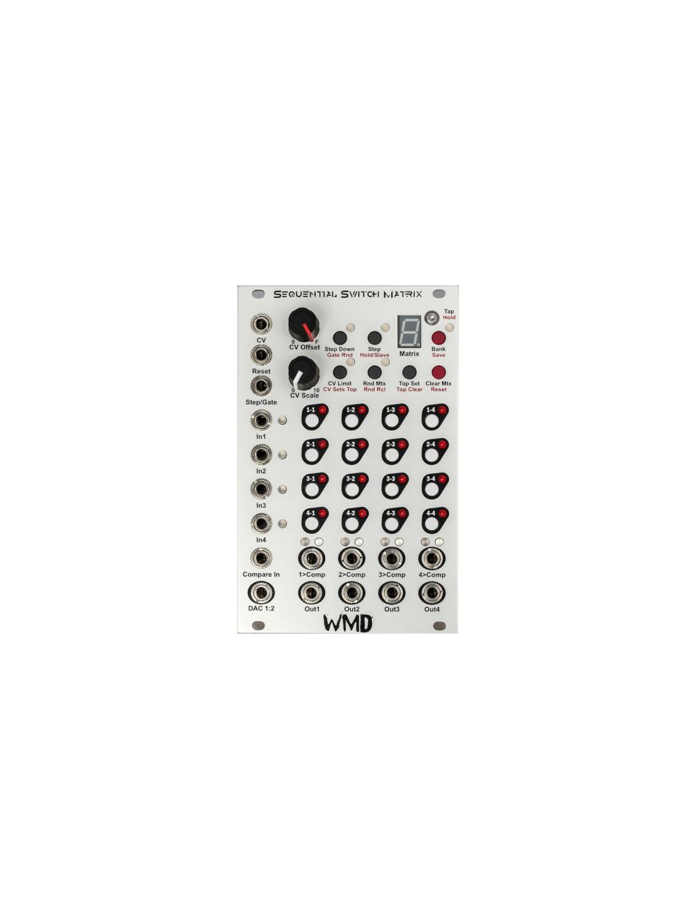

WMD - Sequential Switch Matrix (SSM)
The WMD - Sequential Switch Matrix (SSM) is a mega-project: a sequential switch is designed like your a traditional remote control, except that your sequential switch is controlled by external CV signals, that dictate the switching. Now the SSM realises this in a matrix-fashion: combining various sources for triggering, making new waveforms and shapes at audio rate, it is a lot to have in one truly special module!
Check out the manufacturer's video overview
Introducing the WMD Sequential Switch Matrix: Our take on an essential module.
Four inputs can be routed with individual buttons to four outputs. Those routing settings are stored in an array of matrices that can be sequenced or controlled with CV. Preset routing, feedback loops, chop sequences, trigger blasts (with expander), four-bit-wavetable-synthesis, and dramatic controllable mayhem are all possible.
Features
Four Input Four Output Routing
Inputs Mix to Outputs
16 Matrices per Bank
20Vpp Headroom
Signal Strength and Polarity LEDs
Comparator Input and Outputs
Simultaneous CV and Gate Control
Four Banks With Separate Settings
Randomizing Functions
CV Controlable Top Matrix
Can Slave to MIDI Control Change
26kHz Maximum Switch Frequency
8 Bit DAC Voltage Output
Skiffable PCB Design
16 HP
+80mA/-32mA Current Consumption
Concept
The Sequential Switch Matrix (SSM) is a four input, four output signal routing system. The digitally controlled analog signal paths allow for a variety of routing control options. The open architecture allows for many uses beyond simple signal routing and unity mixing.
Signal Path
The signal path uses 0.1% resistors and will pass precision pitch or other CV signals with minimal gain and offset errors.
Inputs 1 - 4: These inputs accept bipolar +-10V signals before clipping. Signal level will illuminate the adjacent LED; green for positive voltages, red for negative.
Outputs 1 - 4: These outputs (along the bottom) contain the signals from the inputs (summed together) if the routing LED is lit.
Comparator: The Compare In input voltage is compared to each output voltage. If the output is higher than the Compare In voltage, the Comp output will be high (10V gate) for that channel. The blue LED will also be illuminated.
DAC 1:2 Out: This output is generated from the status of the first two columns. It is a weighted Digital to Analog conversion. 1-1 is the most significant bit, carrying a weight of 2.5 volts. 2-1 is exactly half that weight (1.25V). 4-2 is the least significant bit (0.020V). The two columns provide an 8 bit voltage output that is always present.
Control Scheme
BUTTONS OPERATION: Black text for tapping buttons. Red text for push and hold functions. Hold time is about one second. The button will begin toggling after being held more than one second.
Routing Buttons: Tapping the routing buttons will toggle its state. If a button is pushed, it will change for that matrix only. Push and hold has no effect on routing buttons.
Matrix: The current matrix is displayed on the numerical display. It will read 0-9 then A, B, C, D, E, F to represent the 16 matrices in hexidecimal.
Bank: Tapping the Bank button will change banks. LED off is bank 0. Green is bank 1. Red is bank 2. Orange is bank 3. All settings (except for Rnd Rcl) are stored with each bank.
Save: Push and hold to save all banks, matrices and modes to the internal non-volatile memory. Powering down without saving will revert to the last saved settings.
Top: The top matrix will be the reset point when stepping. It is indicated by the decimal point on the Matrix display. Tap the “Top Set” button to set the top to the currently selected matrix. Push and hold (Top Clear) to clear the top, which will step through all 16 matrices.
CV Limit: When the LED is off, CV acts as an offset that can go beyond the Top. When the LED is Green (tap “CV Limit”), the CV is limited to the top, so the CV will be clipped to the Top Matrix.
CV Sets Top: Indicated by the LED being red. The CV will set the top matrix. This allows for CV control of the Top matrix, or CV control over the length of the sequence. CV will no longer change matrices in this mode.
Step Down: When the LED is off, gates and the Step button will step up. When the LED is green, gates and the Step button will step down.
Gate Rnd: Indicated by the LED being red, Gates (only, not the step button) will output a random matrix within the specified Top.
Step: Tapping will step through the matrices.
Hold/Slave: Indicated by the LED being red, this mode stops any CV or Gates from incrementing the matrix counter. You can still step through the Matrices with the buttons, as well as change modes.
If the Macro Machines Memory Manager is connected through the bus board, the SSM will listen for MIDI Control Changes and any received signals will change matrices. When a signal is received, the SSM will slave completely, and can only change matrices and banks from MIDI Control Change.
Clear Mtx: Tapping this will clear the matrix and any I/O connections.
Reset: Push and hold to reset the matrix counter to 0. Remember that CV is not part of the counter and can still offset the matrix that is output.
Rnd Mtx: Tapping this will randomize the currently selected matrix.
Rnd Rcl: Push and hold to light the red LED. When lit, the currently selected matrix will be randomized every time it is recalled via CV, Gate/Step or the Step button. This mode is stored with each matrix.
CV Input: The CV input is attenuated by the CV Scale knob, and added to the CV Offset control.
Step Input: This Trigger input will step the matrix counter depending on the modes set by the buttons per bank.
Reset Input: This Trigger input will set the matrix counter to 0 if counting up, to F if counting down.
Step and Reset are trigger inputs, the rising edge is detected, and the input must fall before another trigger can be detected.
Specs & Notes
Width: SSM 16 HP. Expand 8 HP.
Current consumption: SSM +80mA/-32mA. Expand +40ma/-3mA.
Voltage Levels: Input range +-10V. Output range +-10V. Step/Gate and Reset sense signals at 0.8V.
Operating Frequency: Maximum transition frequency is 26kHz. Pushing buttons at high clock speeds will slow the response as the buttons are debounced.
Compare Input: +-10V. Normaled to 0.5V.
Depth: SSM & Expand - 25mm with connectors
Compliance: The SSM and Expand are RoHS and CE compliant.
Warranty: The SSM and Expand are covered under warranty for 12 months after purchase. Please contact us if you ever have problems. We will take care of you.
Manual is available as a PDF.
Price Match
Did you see it cheaper?
PRICE MATCH
The Low Price Guarantee can be applied for any products that are available in our online store!
The Low Price Guarantee can only be applied for if the other product can be verified to be in stock at our Competitor's shop.
Please send your Price Match inquiry here!
In order to validate the Analogue Zone Low Price Guarantee you will need to be able to present a proof, e.g. the webpage URL of the online store, a flyer, catalogue, etc.
more info...
Shipping to the US
in 3-4 days
SHIPPING TO USA
We are happy to to send shipments to the US.. You can find some of our shipping examples below.
Tracking number provided for all the shipping options!
| Shipping Option | Delivery | Price EUR |
|---|---|---|
| Priority (up to 1 kg) | 6-9 days | 18 |
| Priority (up to 2 kg) | 6-9 days | 25 |
| EMS (up to 1 kg) | 3-4 days | 35 |
| EMS (up to 2 kg) | 3-4 days | 42 |
| EMS (up to 3 kg) | 3-4 days | 50 |
For more specific information click here for the shipping cost calculator, choose the World option, and select the weight.
2-3 eurorack mode usually around 2 kg.
14-days
money back guarantee
RETURN POLYCY
You can return the purchased product 14 days after purchase. All returned items must be in new condition, in their original unaltered box, and must include all packing material, blank warranty cards, manuals and accessories. Analoguezone can only refund the original purchase price. Shipping and handling fees are nonrefundable.
For more detailed information click below.
more...Delivery Times
for EU destinations
DPD Shipping Terms
The shipping price will be calculated during checkout, based on the destination and weight.
Orders placed before 12:00 will be shipped same day!
Tracking number will be provided upon pick-up.
The shipping cost includes insurance up to 520 EUR. If the total value is greater than this, the insurance is 0.4% for the difference.
| Country | Working days |
|---|---|
| Austria, Slovakia | 1 |
| Luxembourg | 2 |
| Germany, Czech Republic, France, Poland, Slovenia | 2-3 |
| Belgium, Netherland, UK | 3 |
| Italy, Latvia, Lithuania, Spain, Sweden | 3-4 |
| Croatia, Denmark, Ireland, Portugal | 4 |
| Estonia | 3-5 |
| Greece, Bulgaria | 4-5 |
| Finland | 5-6 |


Modular/Synths/Studio
+36 1 800 1720