
Mordax - Data
The Mordax - Data is by no mistake the most up-to-date oscilloscope module with plenty of generator and extra utility functions aboard: clocks and audio oscillators are also at your command. Imagine a digital oscilloscope that was reborn as a eurorack module.
The Mordax - Data is by no mistake the most up-to-date oscilloscope module with plenty of generator and extra utility functions aboard: clocks and audio oscillators are also at your command. Imagine a digital oscilloscope that was reborn as a eurorack module.
Mordax - DATA : The multifunction tool for Eurorack modular systems
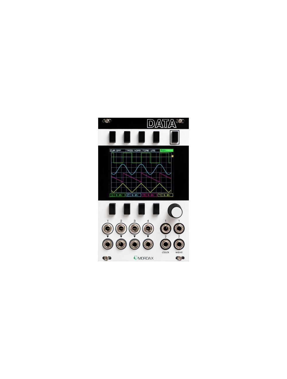
The DATA is a digital platform for testing, measurement, and signal generation in Eurorack modular synthesis systems. It is a modular tool kit, with functions applicable to any system and style.
Use the DATA’s scope to view the interactions between your control voltages and audio signals, allowing you to master your modules by understanding their voltage ranges, control shapes, and parameter responses. Use the DATA’s dual waveform generator to dial in a precisely scaled LFO for CV control, or use the waveform’s frequency “note mode” to effortlessly make dyads (two note chords). Use the DATA’s clock program as a master clock or to divide or multiply an incoming clock signal, sending two different clock outs to gate modules directly or as control to sequencers.
The possibilities of the DATA are basically unlimited; with the included microSD you can update the DATA’s firmware and we can continue to refine and create new programs.
We're pleased to announce we have partnered with Darkplace Manufacturing in Portland, Oregon, for the DATA's circuit board population and assembly, and American Metal Specialties in Milwaukie, Oregon for manufacturing the DATA's faceplate.
The Many Forms of DATA
- 4 Channel Oscilloscope
- Monitor four independent CV or audio channels
- Selectable voltage scale, position, AC/DC coupling, and visibility
- Trigger from any channel, with full scale, user-selectable trigger level
- Time scale ranges from 50µS to 5 seconds per grid square (total range of 600µS to 1 minute of signal across the screen)
- X (time) and Y (voltage) measurement cursors with difference display, allowing for simple measurement and windowing of any input signal
Tuner
Measure the precise frequency of any of the 4 incoming signals with a large frequency display
The tuning display shows your distance from the closest note graphically and as a frequency number
Nearest note is automatically detected and changes while you tune
Voltage Monitor & Source
4 channel input display with real-time voltage readout, a simple CV scope
2 channel manual gate source; hit the bottom buttons one and two for a 0-5V gate out of the CLOCK/GATE outputs 1 & 2 respectively.
2 channel selectable voltage source; dial in -5 to +5 CV values and they are constantly output from the WAVE/CV outputs 1 & 2
Dual Waveform Generator
Two independent oscillator channels, with control over frequency, phase, amplitude and offset (wave center)
Current waveforms: sine, square, saw, triangle, with waveform output display per channel
Frequency range: 4kHz down to 0.01Hz, selected per numeral for quick, precise value input
“Note Mode” frequency selection available independently for either oscillator
CV assignable control over frequency (1V/Octave) and amplitude (digital VCA)
Flexible CV control routing; any of the four input jacks can be freely assigned to any destination, with per destination attenuation (percent value)
Dual Clock Source with Clock Division & Multiplication
“External Sync” or “Internal Clock” modes; use it as a precise and stable master clock, or as a clock processor sync’d to an external clock source
Dual clock outputs, each can be a ratio of the main clock (internal/external),
current div/mult values: x32, x24, x16, x12, x8, x6, x4, x3, x2, 1:1, /2, /3, /4, /5, /6, /8, /12, /16, /24, /32
Beat offset shift for each clock pulse, +/- 96 steps
Clock display bars show the beats of the main clock and two output clocks relative to each other;
shift the offset or change the ratio and the pulses positions change in real-time
Pulse Per Quarter Note (PPQN) of the external clock signal user selectable from 1 to 24,
allowing for sync’ing to a range of sources (and for further changing your output ratios if used creatively!)
Input jacks 1 & 2 act as “Clock Sync” and “Reset” inputs while in “External Sync” mode
and as “CV BPM control” and “Reset” while in “Internal Clock” mode
Input jacks 3 & 4 are user-assignable CV input sources,
which can be assigned to control either of the output clock’s div/mult values and offsets, with selectable attenuation per destination
Spectral Analyzer (single-FFT)
Display the current harmonic content of any of the 4 incoming signals
User-selectable filter window (Square/None, Hann, Bartlett)
Peak frequency bin readout shows you frequency range of the first harmonic (fundamental frequency) in the signal
Spectrograph (multi-FFT)
Display the harmonic content of any of the 4 incoming signals over time
Each column of pixels along the X axis is one frame of the Spectral Analyzer’s display.
User-selectable filter window (Square/None, Hann, Bartlett)
Controls for display clear and run/stop
250 mA +12V
60 mA -12V
0 mA 5V
35 mm Depth
Price Match
Did you see it cheaper?
PRICE MATCH
The Low Price Guarantee can be applied for any products that are available in our online store!
The Low Price Guarantee can only be applied for if the other product can be verified to be in stock at our Competitor's shop.
Please send your Price Match inquiry here!
In order to validate the Analogue Zone Low Price Guarantee you will need to be able to present a proof, e.g. the webpage URL of the online store, a flyer, catalogue, etc.
more info...
Shipping to the US
in 3-4 days
SHIPPING TO USA
We are happy to to send shipments to the US.. You can find some of our shipping examples below.
Tracking number provided for all the shipping options!
| Shipping Option | Delivery | Price EUR |
|---|---|---|
| Priority (up to 1 kg) | 6-9 days | 18 |
| Priority (up to 2 kg) | 6-9 days | 25 |
| EMS (up to 1 kg) | 3-4 days | 35 |
| EMS (up to 2 kg) | 3-4 days | 42 |
| EMS (up to 3 kg) | 3-4 days | 50 |
For more specific information click here for the shipping cost calculator, choose the World option, and select the weight.
2-3 eurorack mode usually around 2 kg.
14-days
money back guarantee
RETURN POLYCY
You can return the purchased product 14 days after purchase. All returned items must be in new condition, in their original unaltered box, and must include all packing material, blank warranty cards, manuals and accessories. Analoguezone can only refund the original purchase price. Shipping and handling fees are nonrefundable.
For more detailed information click below.
more...Delivery Times
for EU destinations
DPD Shipping Terms
The shipping price will be calculated during checkout, based on the destination and weight.
Orders placed before 12:00 will be shipped same day!
Tracking number will be provided upon pick-up.
The shipping cost includes insurance up to 520 EUR. If the total value is greater than this, the insurance is 0.4% for the difference.
| Country | Working days |
|---|---|
| Austria, Slovakia | 1 |
| Luxembourg | 2 |
| Germany, Czech Republic, France, Poland, Slovenia | 2-3 |
| Belgium, Netherland, UK | 3 |
| Italy, Latvia, Lithuania, Spain, Sweden | 3-4 |
| Croatia, Denmark, Ireland, Portugal | 4 |
| Estonia | 3-5 |
| Greece, Bulgaria | 4-5 |
| Finland | 5-6 |


Modular/Synths/Studio
+36 1 800 1720