
ADDAC 208 - Comparator & Rectifiers
ADDAC 208 - Comparator & Rectifiers
A Comparator is an electronic circuit that compares two voltages and switches its output to indicate which is larger. The Comparator operates between -10 or +10V The Output is always -10V if below Threshold and +10V if above Threshold.
A Rectifier is an electronic circuit that is used to transform AC signals to an equivalent DC signal while removing one of it’s polarities, i.e. Positive rectification excludes negative signals and vice-versa.
Both sections can be used to change the shape of any waveform as well as it’s harmonic content.
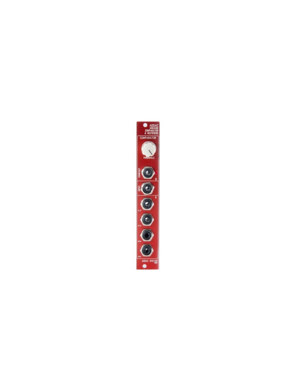
FRONT PANEL:
1 Comparator Threshold Knob
1 Comparator Jack Output
2 Comparator Monitor Led1 Common Signal Jack Input
4 Rectificated Outputs
FEATURES:
4HP totally analog module.
Comparator with Threshold Knob
4 Precision Rectificated Outputs::
- Positive Half Rectification
- Positive Full Rectification
- Negative Half Rectification
- Negative Full Rectification
EXTRA FEATURES/ APPLICATIONS:
Comparator can be used with VCO’s to create a Square Wave with PWM control
Comparator can also be used with complex audio signals for a “Fuzz” effect.
Full Rectification can be used to double a VCO frequency.
Specs
MECHANICAL:
Format: Eurorack
Width: 4 HP
Depth: 2.5 cm
CONTROL VOLTAGE I/O:
CV inputs: ± 10v
CV outputs: ±10v
ELECTRICAL:
Max current: 30mA
Compatible with +-12v and +-15v power supplies
Bus Board Cable: 8 × 2 IDC (Doepfer style) connector
Price Match
Did you see it cheaper?
PRICE MATCH
The Low Price Guarantee can be applied for any products that are available in our online store!
The Low Price Guarantee can only be applied for if the other product can be verified to be in stock at our Competitor's shop.
Please send your Price Match inquiry here!
In order to validate the Analogue Zone Low Price Guarantee you will need to be able to present a proof, e.g. the webpage URL of the online store, a flyer, catalogue, etc.
more info...
Shipping to the US
in 3-4 days
SHIPPING TO USA
We are happy to to send shipments to the US.. You can find some of our shipping examples below.
Tracking number provided for all the shipping options!
| Shipping Option | Delivery | Price EUR |
|---|---|---|
| Priority (up to 1 kg) | 6-9 days | 18 |
| Priority (up to 2 kg) | 6-9 days | 25 |
| EMS (up to 1 kg) | 3-4 days | 35 |
| EMS (up to 2 kg) | 3-4 days | 42 |
| EMS (up to 3 kg) | 3-4 days | 50 |
For more specific information click here for the shipping cost calculator, choose the World option, and select the weight.
2-3 eurorack mode usually around 2 kg.
14-days
money back guarantee
RETURN POLYCY
You can return the purchased product 14 days after purchase. All returned items must be in new condition, in their original unaltered box, and must include all packing material, blank warranty cards, manuals and accessories. Analoguezone can only refund the original purchase price. Shipping and handling fees are nonrefundable.
For more detailed information click below.
more...Delivery Times
for EU destinations
DPD Shipping Terms
The shipping price will be calculated during checkout, based on the destination and weight.
Orders placed before 12:00 will be shipped same day!
Tracking number will be provided upon pick-up.
The shipping cost includes insurance up to 520 EUR. If the total value is greater than this, the insurance is 0.4% for the difference.
| Country | Working days |
|---|---|
| Austria, Slovakia | 1 |
| Luxembourg | 2 |
| Germany, Czech Republic, France, Poland, Slovenia | 2-3 |
| Belgium, Netherland, UK | 3 |
| Italy, Latvia, Lithuania, Spain, Sweden | 3-4 |
| Croatia, Denmark, Ireland, Portugal | 4 |
| Estonia | 3-5 |
| Greece, Bulgaria | 4-5 |
| Finland | 5-6 |


Modular/Synths/Studio
+36 1 800 1720